It’s been a dream of mine since I bought my first home. A dream of wires and connectivity everywhere. A dream of having constant and consistent connectivity in every room of my home. Don’t get me wrong, wireless is great and over the years it’s definitely come a long way to satisfying my wants for more bandwidth, but success varies and reliability is one thing that can never be guaranteed – the further away from the access point you are, the less you’re going to get of either. I once tried to stream a DVD over my 802.11n wireless connection and was deeply disappointed that not even with the multi-stream router capable of 450mbps could make this 100% reliable. After many years, I finally had the chance to make this dream a reality.
If you’re looking to do something similar in your home, I will say that the adventure is arduous and full of pain, and certainly not without surprises at every corner. You might think a drop will be a straight shot, or that the wall will be empty but it’s quite likely that neither are true. Be prepared, get the right tools, and be ready to cut holes in your walls that are bigger than you had originally thought you would. Herein I provide a list of tools that you’ll need, tips to make the process easier, and comments on the issues I encountered along the way. I posted a series of photos to illustrate the progress along the way as well; they’re at the end of this page.
Tools and Supplies
- A plan – First and foremost. You need to know where you’re going to run the wires to, where they will terminate, and how many of them you’re going to run. Be flexible! I ended up moving a few runs after I started because I found certain locations that I originally wanted less than ideal to get wires to (less than ideal means household acceptance factor = 0 when presenting the need to rip a whole wall out)
- The Basics – ladder, drill, tape (electrical or duct tape), drywall saw
- Wire cutters, block punching tool, cable strippers – I had the block punch tool already but I did purchase a nice wire stripper for coax/CAT5/6 that made stripping back the insulation on wires a lot easier
- Fish tape, fish rods; at least one of each – I used a retractable 50ft fish tape (plastic/round) and a set of glowing fish rods
- Auger bit – a super long semi-flexible one used to drill holes in 2x4s in the attic and in the wall headers between my 1st/2nd stories
- Conduit – I used plastic conduit because it’s cheap and can be fed through walls in weird directions; it’s semi rigid and great for future proofing
- A whole lot of wire – based on my plan, the runs would primarily consist of 4 CAT6, 2 RG6Q and 2 sets of 14×2 audio wires to each drop point. I estimated my needs based on that and the height of walls and width of the rooms. If you don’t have blueprints you should measure with a measuring tape to get a rough estimate. Then add at least 10% to that number to cover slack (you’ll need it) and any unforeseen obstacles you’ll need to get around
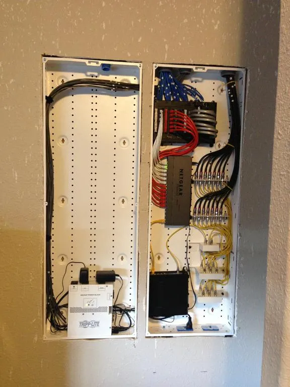
- Structured wiring cabinets – I opted for the in-wall variety from Leviton, and got two of the 40″ models for added space. Go big! You don’t want to do this again!
- Patch panels – one for CAT6 (Data) and one for telephone (egad, wired phones – history proofing rather than future proofing). A biggie – you can do without but it’s highly recommended you don’t because these make it MUCH easier to reconfigure and allocate the lines going to each room as needed
- F Connector Terminal Blocks and cable splitters – “patch panels” for coaxial cable, which again make it SO much easier to reconfigure and reroute cable lines after you’re done. I got enough splitters to handle the incoming line, an initial split for cable modem support, and then two additional splitters to cover creating two independent cable networks (think satellite+standard cable)
- Low Voltage Mounting Brackets – these give you something to screw the wall plates into without have to get a box that attaches to the 2x4s in your walls
- Wall plates, Keystone Jacks, Connectors – get 1- or 2-gang with enough sockets to plug all the jacks in for the wires you’re running. I got 4x RJ45 jacks (four different colors) and 2x coax (again different colors) with room to add two additional RCA jacks for audio connections in each room/for each drop point. I got a big box of F connectors for the coaxial runs also.
- Labels! Oh my god, labels. DO NOT FORGET LABELS. Label every single wire as you’re pulling it. I started with a run number, and then using a wire tracer, I identified each individual line with a number code so I knew which line went where and which one it was in every room
- Miscellaneous – PVC pipe, small chunks of 2×4 and a couple of boxes. I created a sort of wiring rig that I used to pull the wire off each spool as I was running it. SO much easier to run the wires without things getting tangled or kinked
- And finally – lots of guts, patience, and a willingness to work your ass off for a few days, unless you really LIKE holes in the walls and drywall dust everywhere
As you can see, the list of supplies is long. You can do the job without all this stuff, and indeed if your plan is a simple one, definitely adjust according to your needs. I tried to plan for as far into the future as my mind and budget would allow. All told I think I spent around $1500-$2000 in parts and equipment, including the network switch, the UPS (I managed to cram one in the structured wiring cabinet – yay) and other miscellaneous hardware.
Tips and Issues
Now, for the tips and issues. Some of these are do or die and others are just sanity preservation measures. Hopefully most of them will help you in one way or another, either to keep you from making the same mistakes I made or to help you plan for all possibilities.
- The plan is just that: a plan. Until you get cracking, you can imagine how things will go all you want but I guarantee you’ll come across something that will force an adjustment to the plan. I had plans for two runs that I ultimately decided not to run after I started because I realized just how difficult it was going to be to pull them off. I’ve found only one of them would have been useful to this day but I’m still happy I chose not to run it since it would have required tearing out drywall in areas that are very much front and center in the home. Wireless is sufficient in this particular area.
- Existing wires will not be run in any logical direction – guaranteed. Before I started I thought the incoming cable and telephone wires ran up a side wall directly into the attic. I could see them in the attic where I expected them to be. But the route they took in getting there was completely unexpected and required the removal of more drywall than I ever would have imagined to track them down. You could mitigate this potential problem with a wire tracer, but even then I don’t think that would have helped here. It was easier and faster to cut a few more holes to pin down their location. You might get lucky, and you might find that the guys who wired your house were all out high when they decided where to run these wires. Be prepared to explore some.
- Use the architecture of your house to your advantage. My original plan had the structured wiring cabinets in a closet on the second floor. It turns out that it was actually easier to put them in a room on the first floor, because in the second location I had easy access to power AND an open area behind the walls that ran all the way to the attic. This made for easy initial access, easy pulling, future access and easy power to the cabinets. I was able to add more conduit to future proof things going this way as well. I used marginally more cable in doing so though, so I was glad I bought more cable than was originally estimated.
- Expect to run into two things in most of the walls when running cable through them: insulation and fire stops. Inside walls are less likely to have insulation in them, which makes running wires a lot easier, however all modern homes have fire stops built into the walls. These are half/full size 2x4s that are nailed in horizontally between the studs in your walls and they’re designed to slow the travel of fire in the unfortunate event that one does start. This is great for your escape plan, but a real pain in the ass for running wires. Best case is you’ll be able to finagle the wire around them – worst case is more opening of drywall. Either way, be prepared to handle that aspect of in wall wire runs.
- Building codes – every municipality has them and you absolutely should do your due diligence in researching them before you start. There are few when it comes to running low voltage wires but there are some that will affect you and they’re there to protect you. A couple key ones: remember than when you put holes in wall headers and in fire stops, you need to fill those holes with a suitable material after you’ve run wires through them – this is generally accomplished using fire stop foam which you spray in and will expand to fill any gaps left over from your drilling expeditions. Likewise, when running wire through floor joists, try to keep the runs perpendicular to the joists as much as possible, and when crossing through them, use the existing knock out holes rather than drilling new ones through the joists. These reduces the integrity of the floor joists and will cause things like creaks when you walk across them (or worst case, will cause them to fail entirely if you are really careless).
- Be as gentle as possible when running wires and heed these general tips – don’t yank the wires, twist them, tie them together, kink them or be overly abusive with them. They are sensitive to these things and doing so will impact performance. You might think running CAT6 will guarantee you 10GBps in the future but if you kink the wire it’s highly unlikely it will ever be able to provide that sort of bandwidth. The internal wires are twisted to perfection in order to meet the CAT specification and being reckless can and will pull them out of tolerance, leading to reduced bandwidth and ultimately link failure. You don’t want to run all this wire only to find out you can only get 10MBps out of it, or worse to find out that you need to replace an entire run because it got stuck and you decided to hang off it and swing like a monkey to get it through.
- Terminating is a bitch. Pure and simple. CAT6 has 8 distinct wires that need to be punched down and while a punch tool makes this easier (a must have) it’s still quite monotonous. Terminating coaxial is even worse and to be honest, downright painful after you terminate the ends of 14 different lines. There are tools for this! Use them! Your hands will thank you, I promise!
- As a corollary to terminating is a bitch, don’t skimp on the patch panels. After you blister your fingers terminating all these runs, you don’t want to EVER have to go back and do it again simply because you decided that the 4th line you’d only ever use for network connections might suddenly become useful as a telephone or VOIP line, or as an HDMI extension, or whatever. Having the lines terminating at a patch panel makes these adjustments completely painless. Just swap a patch cable out for another and plug it in where it needs to go – it’s that easy with a patch panel
- If you suck at drywall repair, hire someone who doesn’t. Your family will thank you. You won’t cringe when you see the seems in the wall every time you walk by that crappy repair job you did. It will haunt you for as long as you live in the house!
- Future proofing… now that you’ve done all this hard work, when you can it pays to add that extra little bit to protect your investment. Use conduit where you can. Run pull strings where you can’t. Leave a 1 1/2 foot “service loop” at each end of each run as slack to make adjustments or relocate wall plates. Pull more wire than you think you’ll ever use (remember CAT5/6 can be used to run Ethernet, telephone lines, VOIP lines, serial lines, HDMI video, and more – who knows what the future holds).
- Testing… can’t say this enough but after all this hard work you need to test each of the lines to ensure that all of your punch downs are good and that you get a proper link on all the different pairs of each CAT5/6 line you ran. At the bare minimum test the link to ensure it’s solid with a cheap CAT5 cable tester. If you want to get all fancy you go get one of those fancy professional testers that will verify the available bandwidth of every line to ensure it’s up to snuff for your 1GBps connections and the future 10Gbps+ connections that you might really need (want) someday.
Now with all of that out of the way, it’s time to sit back and enjoy the fruits of your labor. Stop worrying about all the WiFi hotspots your neighbors had installed on the same channel, get your dedicated bandwidth, run your phones the way you want them, run cable to Johnny’s bedroom and satellite to yours. Do whatever you want and know that you have all the bandwidth and connectivity you could ever need without worrying about whether it will work “this time”. Brag to your friends that you have a bad ass home network infrastructure that makes theirs look like child’s play. And when you go to sell your house put that on the listing to attract and entice other geeks into paying more for your house because it’s all already there for them to use.
I hope that someone out there benefits from the fun I had in getting my home wired up and jamming!
Until then – party on Wayne!
The Build, in Photos
From the original Imgur album: With a plan, 40+ hours, $1500 for supplies and the desire to put holes in walls, you too can retrofit your home with a business like network infrastructure!
Wiring between cabinets
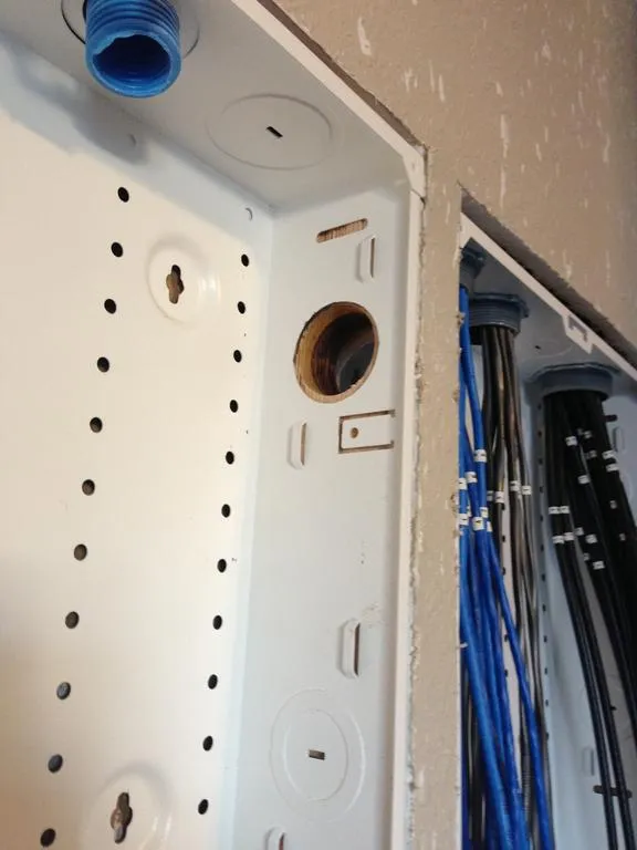
I used a hole saw drill bit to clear out holes for each of the three knockouts the cabinets had.
Ready, Set, GO!
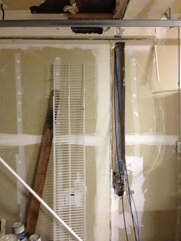
The process started with the main run to the demarcation point. Here you can see we tore out the drywall (this is in the garage) and started with 2 runs each of CAT6 (for telco/data services) and RG6-QS (for cable/sat).
Where do those wires go?
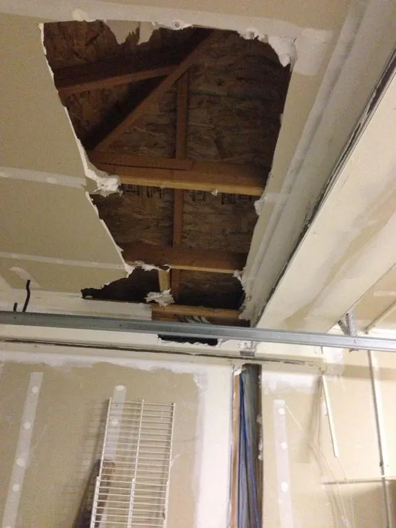
More drywall tear out in the garage. Found out through a bit of trial and error (which you generally can avoid by using a decent quality wire tracer) that the wires from the demarcation do not just go straight up the side wall and into the attic… The wires were actually come back about 5 feet towards the camera in this picture, then up the second story wall, into the attic.
Found them wires!
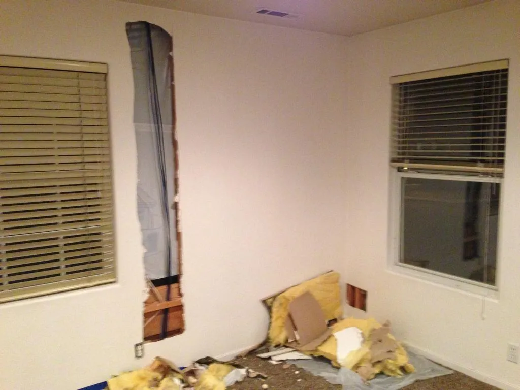
This is the second story room where the main lines run. You can see the wires running through the wall on the left. On the right you can see the hole we put in the wall based on the assumption that those wires just went straight up from the first floor. Ooops. That hole on the left really didn’t need to be that big but it certainly made running the wires easier.
Down we go…
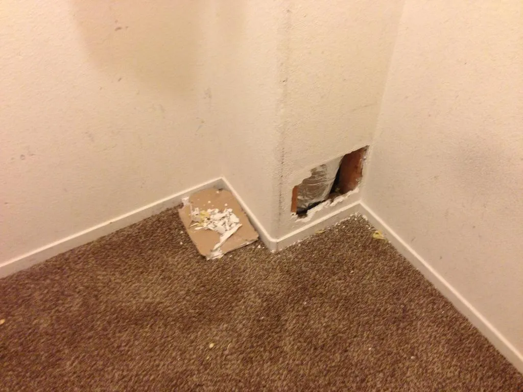
This is the closet in one of the upstairs bedrooms, and is the main chase from the attic back down to the first floor room/closet where I decided to put the structured wiring cabinets. The majority of the lines we ran come down from the attic alongside the duct you can see in the wall here. We used a combination of a nylon fishtape plus 15ft fish rod to get the wires up from the first floor and into the attic.
Almost to the cabinet
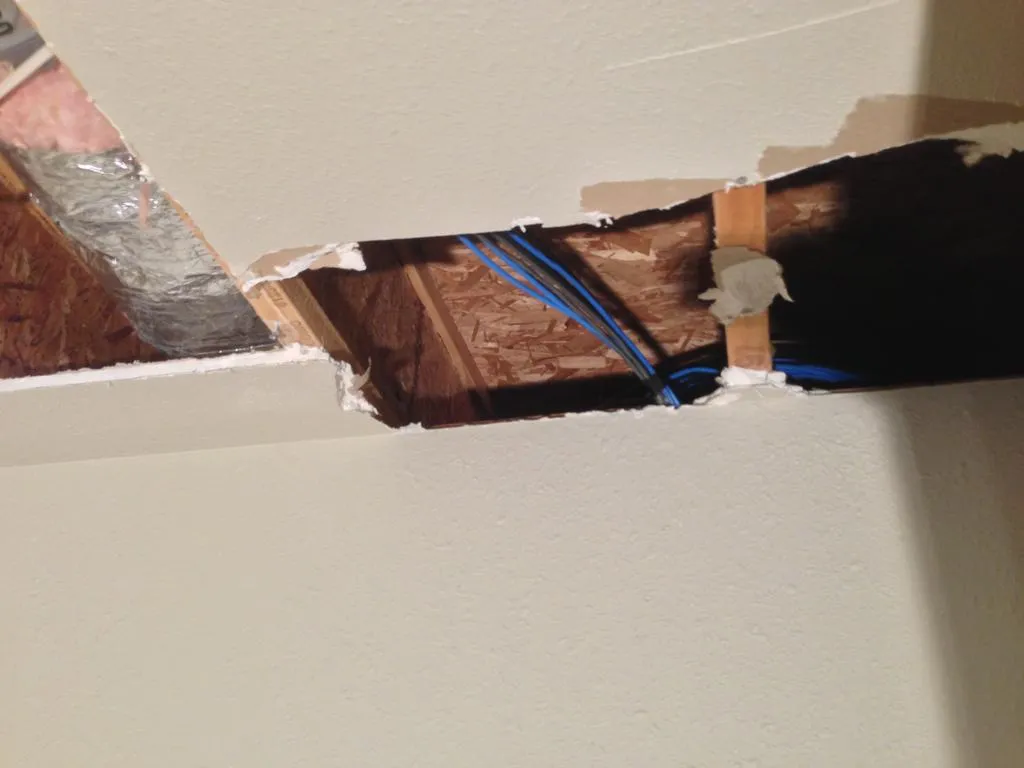
Here you can see the ceiling of the first floor room where the cabinets are locating. Far left you can see the duct from the previous photo, and some wires. The wall in the photo is the closet in the first floor room, and directly below is the planned location for the wiring cabinets.
Where the cabinets will go
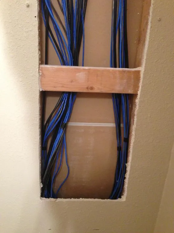
We cut out the wall based on the measurements of the cabinets (I planned for two 42” cabinets). Here you can see one of the in-wall features that can really make running wires through walls a nightmare - the fire block. We ultimately removed this one, but in a couple of the other rooms, these made fishing the wire through the walls a bit of an adventure. Do not forget to label each bundle of wires you pull as you finish each run!
The wiring rig
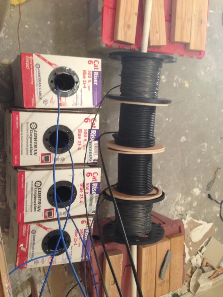
You can see the little rig I setup to make pulling the wires as easy as possible. 4 boxes of CAT6 (500ft each), two rolls of RG6-QS and two rolls of 14/2 speaker wire… In total we ran a little over 2,000ft of wire through the walls over the course of a 12 hour day.
Another shot of the “wiring rig”
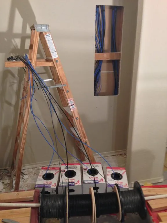
This is another shot of the wiring rig. All of the runs, with the exception of the main run from the demarcation, started here. The wires were bound using electrical tape and the strategy there was to start with one wire, and tape the next wire about 3 inches back on the first, doing the same for the rest so you ended up an assembly that was easier to guide through the holes in the 2x4s in the wall headers and floorboards.
First room run, done!
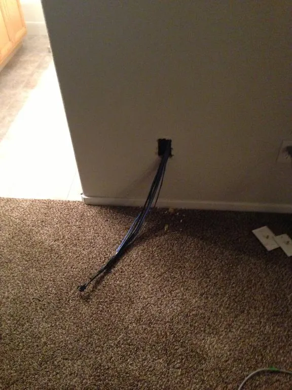
This is a shot of the first upstairs room, drop completed. For most of the runs we used existing wire drops to place the new wires (mostly the old cable TV drops). In most cases you can actually use the existing wires to help pull your new cables through, but because of the sheer amount of cables we pulled to each room, we had to increase the size of the holes in the wall headers to accomodate, which meant pulling the existing wires out. The fish rods came in handy for getting the cable through here.
A special run
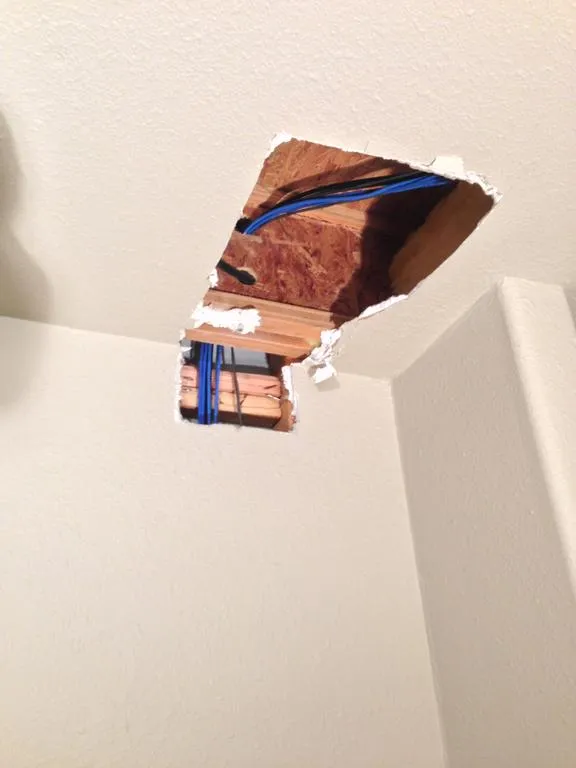
The approach we used for the downstairs room where the cabinets are located was a little bit different from the rest of the rooms. This is the only run that didn’t go through the attic. This hole is about 6 feet away from the closet where the cabinets went, and we used a 6 foot flexible drill bit to clear out a hole in each of the floor joists between this wall and the wall leading down to the cabinet. Here you can see the wire bundle running through the ceiling and entering the wall down to where the wall plate will be located.
The last run…
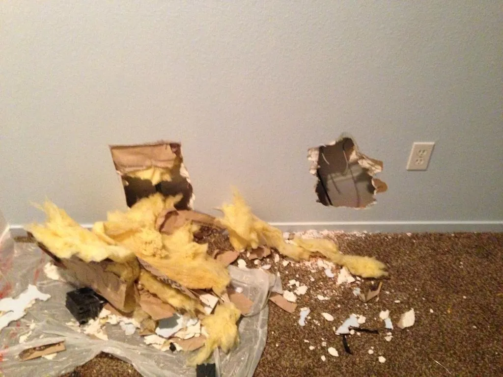
We saved the hardest run for last - the room to the first floor family room. Runs that traverse floors are especially fun, and even more so when the wall you want to drop the line through is an exterior wall. This one was tougher than the main line because we didn’t have the advantage of starting in the garage where the drywall is unfinished - we didn’t want to punch holes in the wall in the family room where it would be more difficult to hide them.
This shot is of the second floor bedroom directly above the downstairs family room, and you can see that we ended up with two holes in the wall because of another bad assumption. Do not assume that the wires are run vertically in straight lines! In our case the lines ran up the first floor wall, then horizontally for a few feet, then up the second story wall… Luckily these repairs can be easily hidden behind a dresser or a bed.
The wall plate
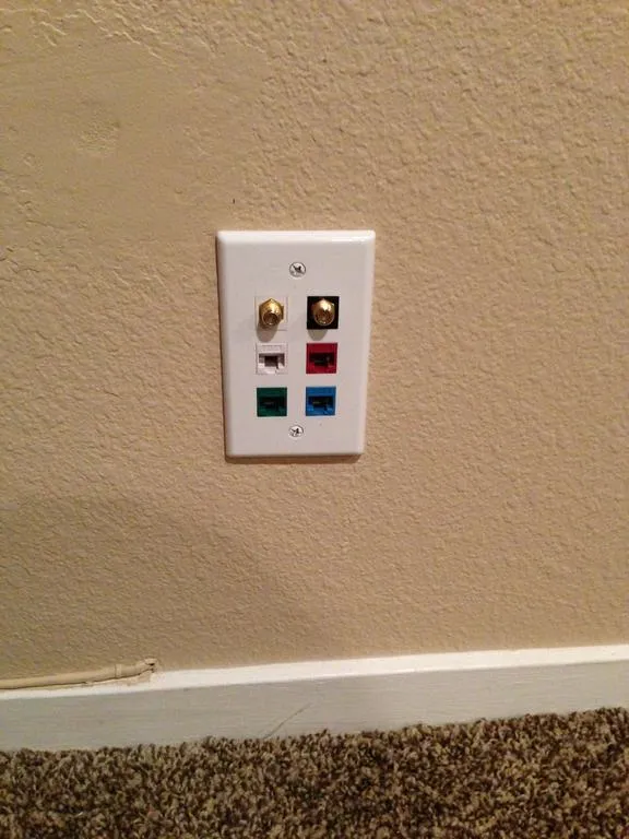
An example of a finished wall plate installation. I ordered all the parts for these from Monoprice and saved a bundle compared to comparable parts from Leviton. This was the final configuration for all of the rooms (minus the 14/2 audio lines which I left in the wall for now) - 2 RG6-QS and 4 CAT6 runs.
First cabinet installed
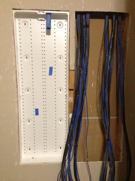
Second hole in wall was cut and fire blocks removed. First cabinet installed. In most cases this should go pretty smoothly, but be prepared for a tight fit between the studs. They’re not always exactly on-center, and in our case it required some work to “shave” down the stud a bit to get the cabinet to fit properly. You’ll notice the little blue tube sticking out the top of the cabinet here - we ran a 2-inch rigid plastic tube from the cabinet to the attic here in an effort to make pulling wires later a little bit easier. I anticipate that some minor additions will be required to handle some alarm wiring and such.
Second cabinet installed
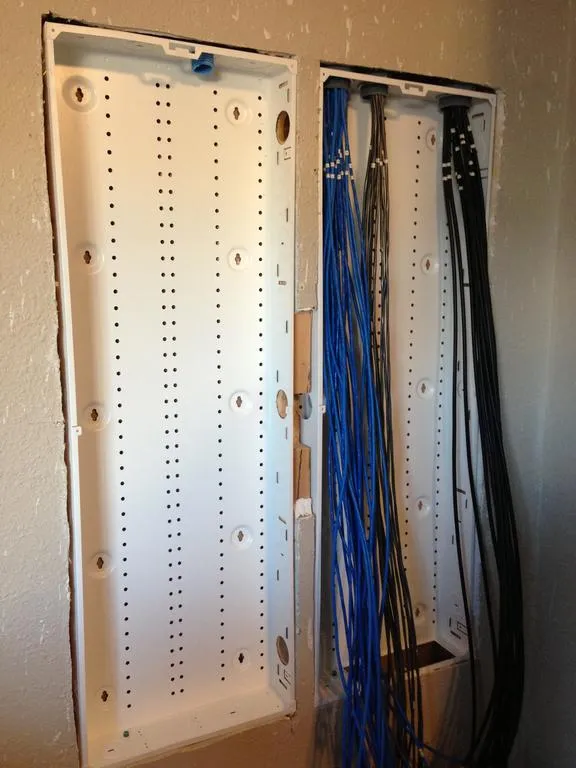
Here you can see the second cabinet installed with the wires dropped through the ports in the top. I used some 2in and 1.5in PVC terminal adapters to help protect the wires from the sharp edges of the wiring cabinet. You’ll notice also that the wires have been grouped according to type, and there are little white labels on each now. I had a helper and used a wire tracer to confirm which wire went to each port in the runs to the room. Labeling where each run went to early on made this process A LOT easier.
Category 6 Patch Panel
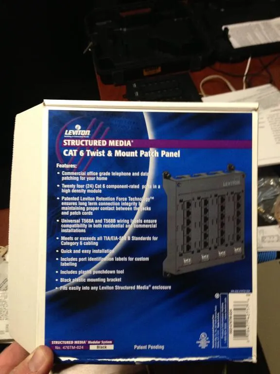
Since I used Leviton panels, the easiest choice was to get Leviton components to install. I opted for a CAT6 patch panel since I used CAT6 wiring throughout. I highly recommend using a patch panel versus terminating your runs with RJ45 connectors - this makes the entire installation very flexible should you change your mind on how the runs will be utilized later on.
Telephone Distribution Panel
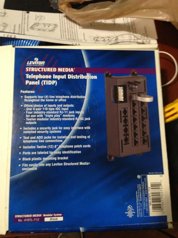
In the age of VOIP you certainly don’t need a normal telephone jack anymore, but I opted to invest in this panel to make distribution of that VOIP or a standard land line that much easier. This panel allows you to bring in up to 4 four lines from any source, hard line or VOIP, and then patch those into the CAT6 panel in any configuration you like.
Wiring up the patch panel
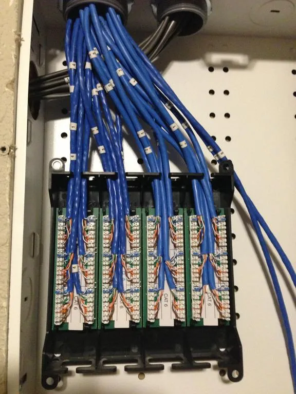
The wire labels came in very handy here, and the patch panel is nice because it is setup to hang on the wiring cabinet while you punch down each of the wires. A standard punch tool makes this job a lot easier, though if you’d prefer not to buy one the panel comes with a plastic tool you can use. I was careful not expose to much of the wire, and more importantly, to keep the twist in each wire all the way up to the wiring block.
Patch panel mounted!
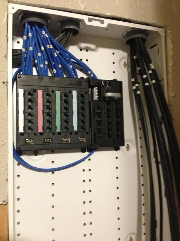
After punching in all the CAT6 lines I simply twisted the panel and mounted using the Leviton push-lock pins provided. You can see the telephone distribution block mounted here also. The blue lines wrapped around both are the main lines from the demarcation point. I don’t need this wired up at this point so I left them there for future use.
Cable Termination Block
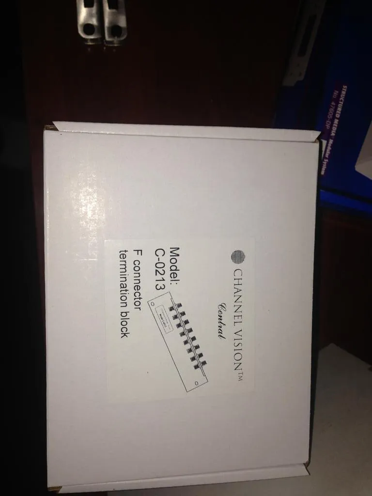
In the spirit of keeping the entire system flexible, I opted to terminate all of the coaxial (RG6) runs using a termination block. This is similar to a patch panel for Ethernet, allowing you to terminate the cable lines once, and then patch them over to a splitter or some other device as needed. I bought two of these, and luckily the Channel Vision components mount easily using the same mounting holes as the Leviton components did.
Splitter
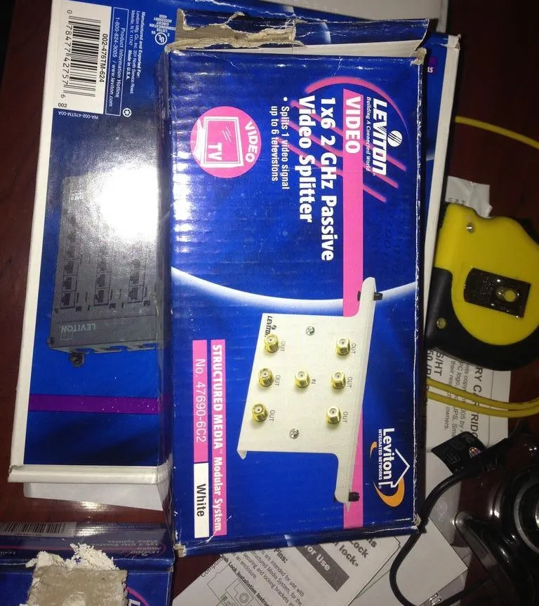
I also bought a couple of six way, non-powered splitters. Not shown here, but also purchased a two way cable splitter to allow for splitting the cable signal as close to the source as possible for our cable modem. I may opt to upgrade to a powered cable splitter or an amplifier if the signal levels are inadequate.
Coaxial Patching Done!
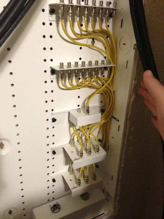
I went ahead with patch from the termination blocks to the splitters prior to terminate all of the coaxial runs. The left most port on the termination blocks correlates to one each of the main lines run from the demarcation, which each port to the right of those being a run to one of the rooms. You can see the two port cable splitter mounted above the six way splitters here.
Coaxial terminations done…
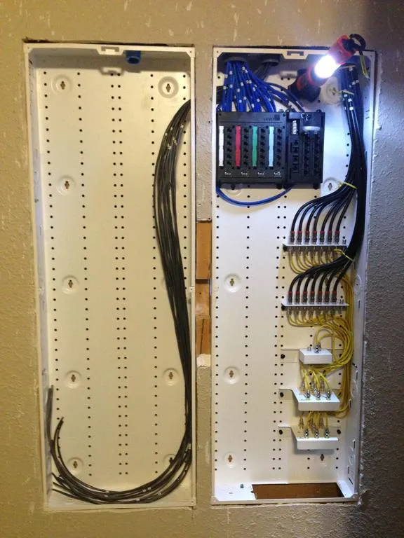
I’d have to say, the biggest pain in the butt, after running the wires, was terminating the coaxial wires. Even with the tools I bought, I poked myself with the copper “stinger” multiple times and ended with blisters from trying to shove those quad shielded wires into the snap on connectors. Here you can see I’m finished with that painstaking process…
Power!
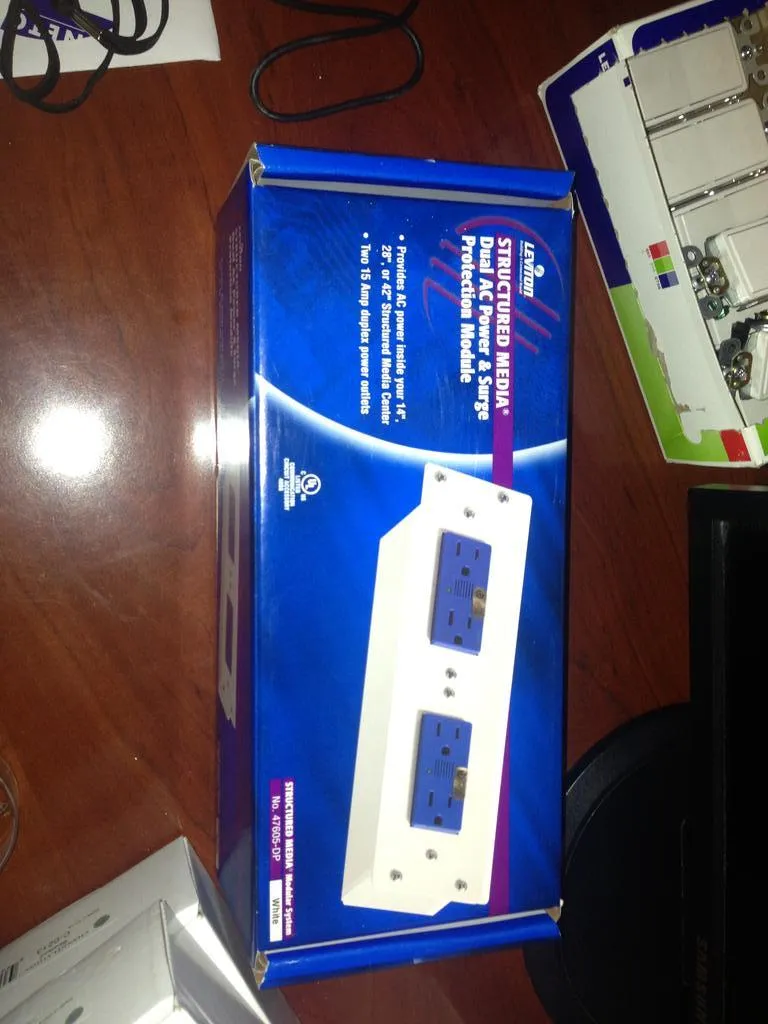
No structured wiring installation would be official without some source of AC power. I opted for a surge suppressed power supply for my cabinets, which you can see here. Luckily the right cabinet is directly above a power socket that feeds the room on the other side, so I was able to tap into the to get the power to this unit.
Wired up and ready to go
And finally, the somewhat completed installation with AC power installed. Still have some work to get the audio features lined out and wired up, and some painting work to do, but you can see the NetGear managed switch installed and mounted (I used velcro to mount it to the cabinet), the patch cables from the ports to the switch (purchased from Monoprice - can’t recommend that place enough), the cable modem and UPS (a Tripp-Lite Model AV550SC, which fits nicely in these enclosures).
It was a lot of time and effort, but at the end of the day, having a solid cable and network infrastructure makes digital life so much better… Wireless is cool but nothing beats a gigabit-per-second wired connection.